Rigid-flex PCBs, 2 to 16 layers
Rigid-flex boards replace connectors and cables with flexible polyimide layers laminated into the rigid sections. That saves space, removes failure points and makes assembly simpler.
We build rigid-flex from 2 to 16 layers, including HDI in the rigid areas and hard gold plating for contacts.
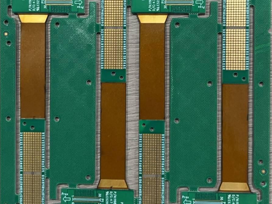
Rigid-flex capability
| Layer count | 2–16 |
|---|---|
| Flex material | Polyimide |
| Flex protection | Coverlay or flexible solder mask |
| Stiffeners | FR-4, polyimide |
| Finish | ENIG, hard gold up to 120 µin |
| HDI in rigid sections | Yes |
| Trace / space | 2/2 mil (0.05 mm) |
How we build rigid-flex
Controlled lamination
Flex cores are laminated with no-flow prepreg so resin stays out of the bend area.
Plasma desmear
Plasma cleaning removes resin from mixed polyimide and FR-4 holes before plating, which is key for reliable vias.
Hard gold contacts
Electrolytic hard gold on contacts and gold fingers for repeated insertion.
Typical uses
- Cameras and optics
- Wearables and medical devices
- Drones
- Industrial sensors
- Aerospace and defense
Maximum values are individual process limits, not a promise that every limit can be combined. A 34-layer, 7-step HDI board is a documented delivered build; projects above this layer count require engineering review.
Explore the builds →HSX / Our factory
The equipment behind the specification.
Original photographs from our Shenzhen factory. Explore the manufacturing process and the equipment used to build and inspect your boards.
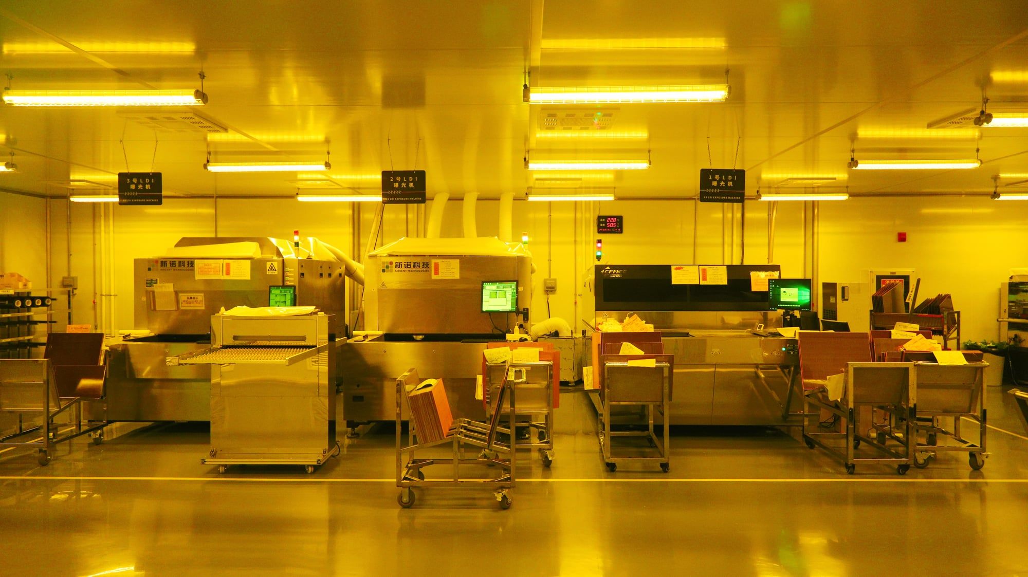
LDI imaging
Direct imaging transfers fine circuit patterns onto the panel. Inner-layer, outer-layer and solder-mask exposure are covered by our LDI equipment.
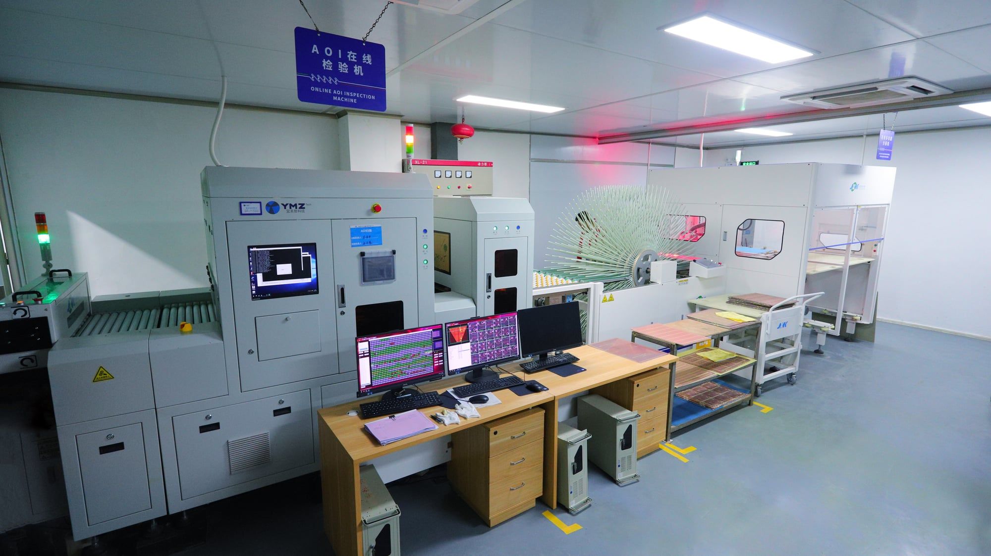
Automatic optical inspection
AOI checks circuit patterns during fabrication. Detected features are reviewed before boards continue through the process.
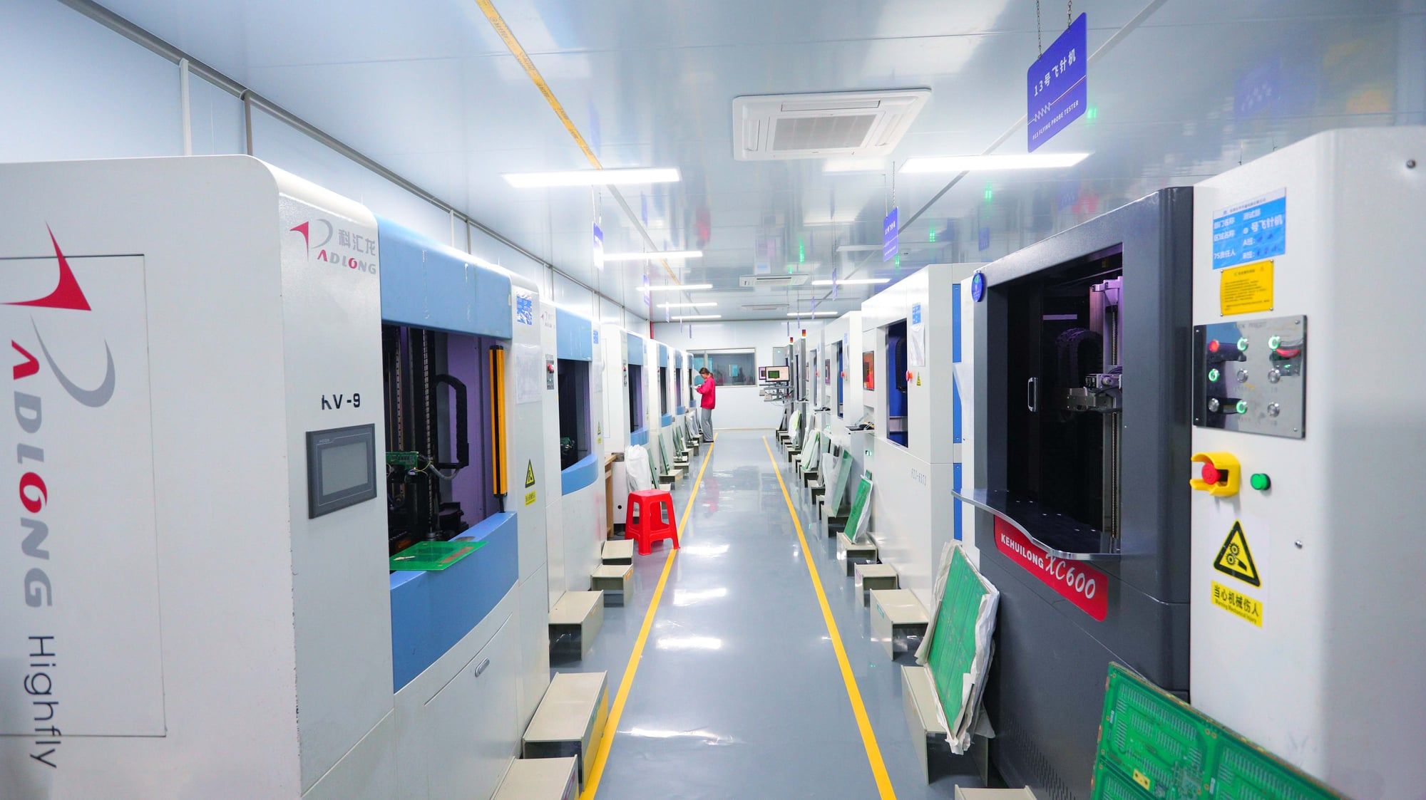
Electrical testing
Every board is tested for electrical opens and shorts before shipment. The factory has 27 flying-probe testers and three fixture testers.
Questions engineers ask us
What is the minimum bend radius?
As a rule of thumb, 10× the flex thickness for single-sided flex and 20× for multilayer flex in static bends. For dynamic flexing send us the bend cycle requirement and we will recommend a construction.
Can the flex section be multilayer?
Yes. Flex sections can have one or more layers. For best flexibility we often recommend an air-gap construction where flex layers are not bonded together in the bend.
What files do you need for rigid-flex?
Gerber or ODB++ with a layer for each rigid and flex outline, a stack-up showing which layers are flex, and the stiffener and coverlay drawings.
Send your design. Let’s build it properly.
Upload Gerber or ODB++, stack-up and quantities. Standard PCB quotes usually take 30 minutes in working hours; HDI, rigid-flex and special materials usually take up to 24 hours.